RF Theory
EM Wave
When a changed particle is accelerated, such as in an anthena, it induces oscillating mutually perpendicular electric and magnetic fields. These fields form an electromagnetic (EM) wave.
Tags:
Source:
RF Theory
RF (Radio Frequency)
RF (or radio frequencies) are the EM waves on the frequency range from 3kHz to 300GHz. They are mostly used in wireless communication and radar applications.
Tags:
Source:
RF Theory
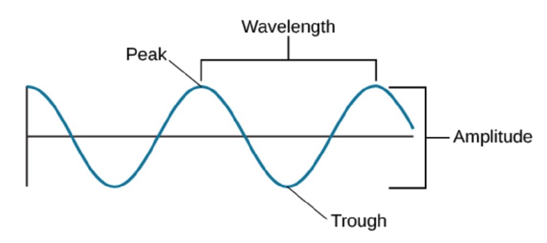
EM Wave
This picture describes basic properties of an EM wave (or any other wave). Amplitude is the height of the wave, wavelength is the peak to peak distance, the highest point is peak, the lowest is through.
Tags:
Source:
RF Theory
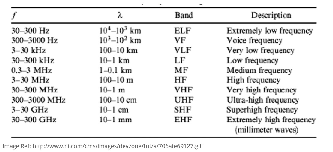
Frequency Bands
EM waves of frequencies within certain ranges get categorized into so called bands. This picture lists the bands and their frequencies:
Tags:
Source:
RF Theory
Frequency & Propagation Distance
Lower frequencies can propagate to longer distances and through obstacles better than higher frequencies, but they can transmit data at lower rate.
Tags:
Source:
RF Theory
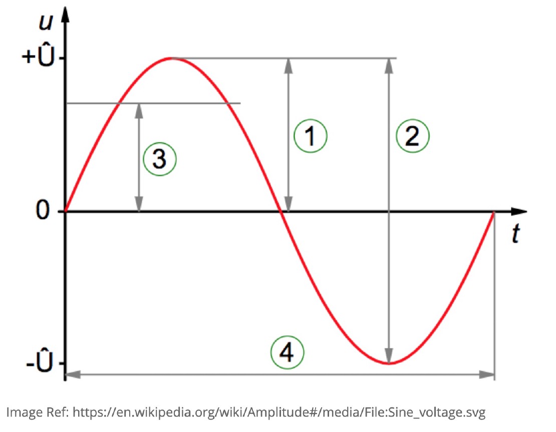
Amplitude
Amplitude of an RF signal is the measure of change of the electric field of the EM wave in time. In the picture, (1) is the peak amplitude, (2) is the peak-to-peak amplitude, (3) is the RMS (root mean square) amplitude, and (4) is the wavelength.
Tags:
Source:
RF Theory
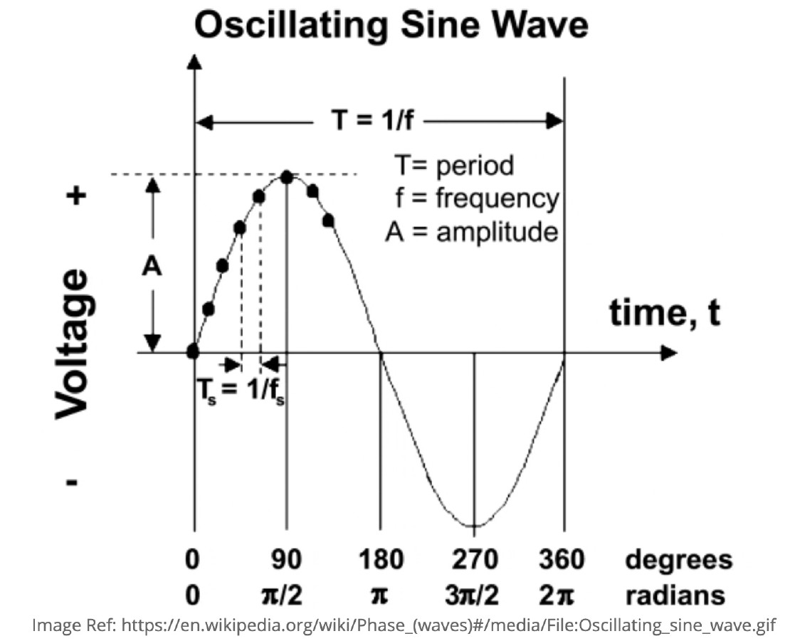
Phase
The phase of an RF wave is the offset of where the wave starts expressed in radians. A wave that is offset by 2 PI (180 degrees) has the opposite waveform compared to the original wave with 0 phase.
Tags:
Source:
RF Theory
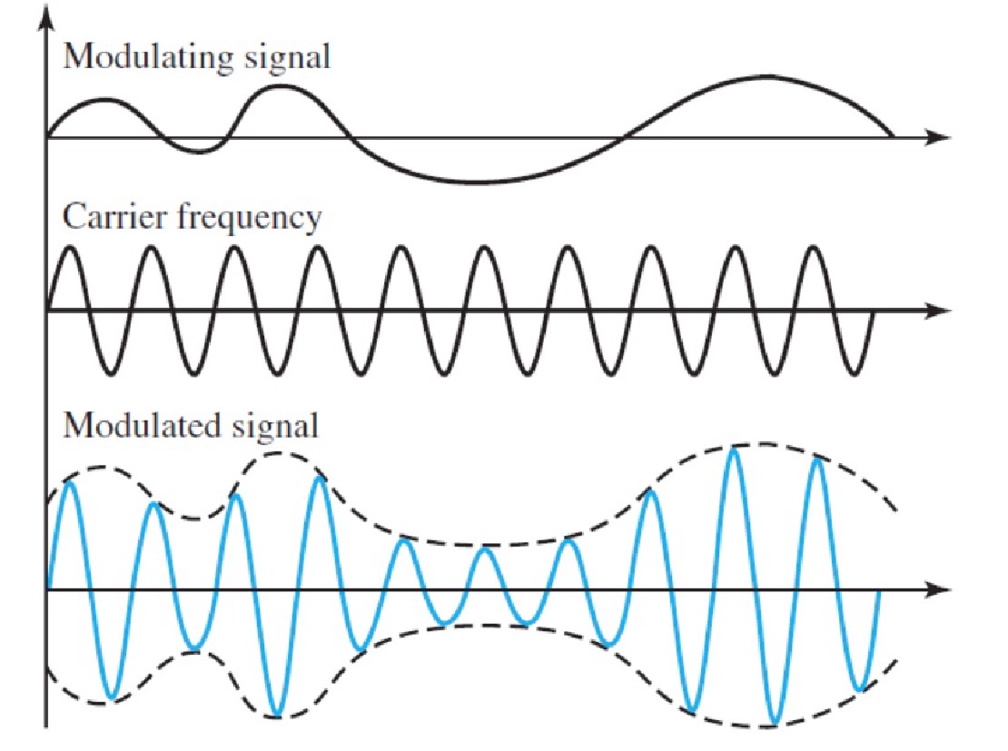
Modulation
In order for EM waves to transmit information, they have to modify the amplitude, frequency and phase characteristics of the wave to encode the information in it. This process is called moduleation and is done by mixing a modulating signal, which contains the information to be transmitted, into a periodic carrier waveform (CW), which propagates the signal through the environment.
Tags:
Source:
RF Theory
Amplitude Modulation
Amplitude modulation (AM) is an analog modulation technique, where the amplitude (signal strength) of the carrier wave is varied in proportion to that of the message signal, such as an audio signal. It’s the earliest modulation method.

Tags:
Source:
RF Theory
Frequency Modulation
Frequency modulation (FM) is the analog encoding of information in a carrier wave by varying the instantaneous frequency of the wave.
Tags:
Source:
RF Theory
Phase Modulation
Phase modulation (PM) is the analog encoding of information in a signal as variations in the instantaneous phase of a carrier wave. Phase modulation is one of the two principal forms of angle modulation, together with frequency modulation.
Tags:
Source:
RF Theory
Digital Modulation
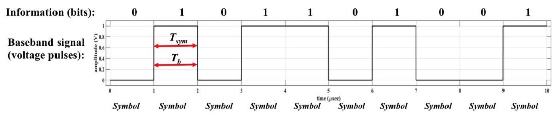
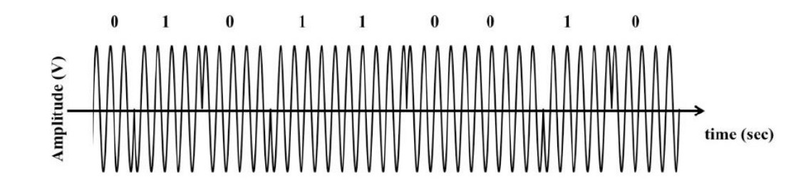
Digital modulation was invented as a way to transmit digital information (0s and 1s) over a carrier wave. To achieve this, discrete RF energy states are used to represent some quantity of the digital information. These states (usually 0 or 1 bits) are transmitted in the form of waveforms that represent the bits. These waveforms are usually referred to as “symbols”. In the image below, there are 10 bits transmitted and they are carried in the 10 symbols.
Tags:
Source:
RF Theory
Symbol Rate & Bit Rate
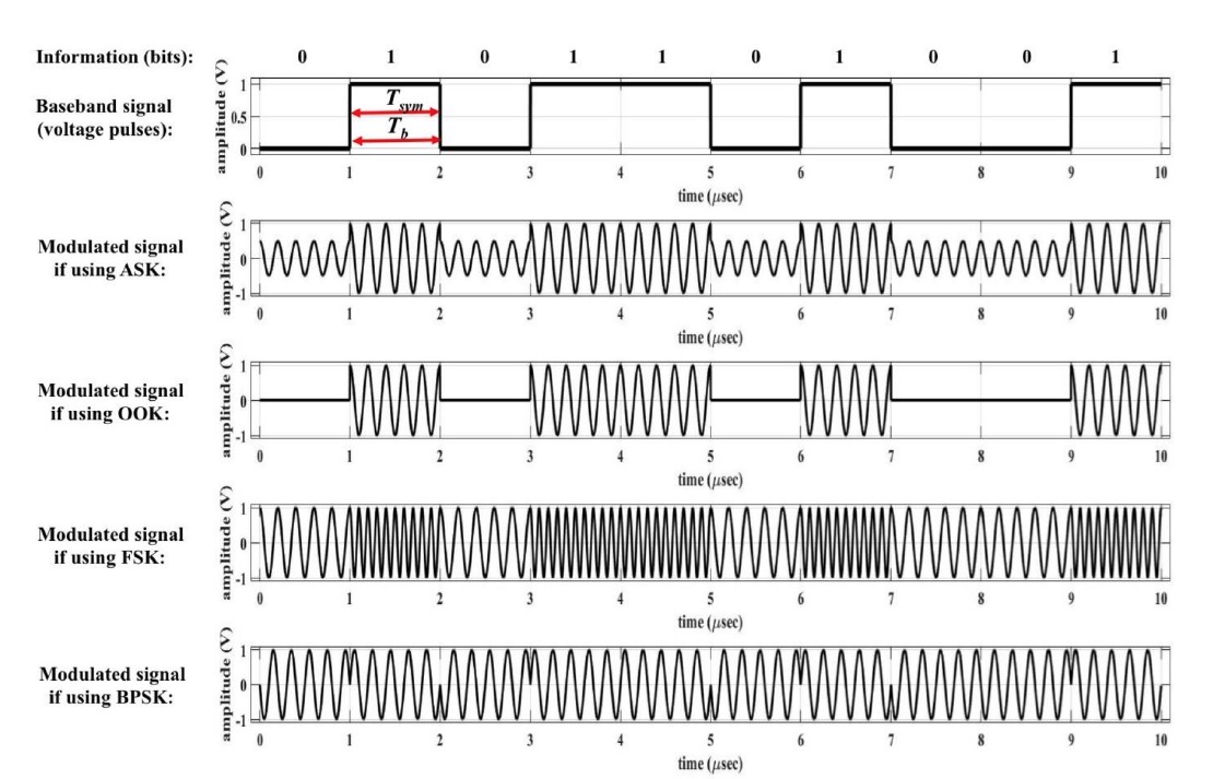
Symbol rate: Rsym=1/Tsym is the rate at which bits are transmitted, where Tsym is the time for one symbol to transmit. Similarly, bit rate is Rb=1/Tb, where Tb is the time to transmit one bit. In the image below, Tsym=Tb. If N is the number of bits per symbol, then Rb=N*Rsym. If M is the number of different available symbols (2 (0 and 1) in the example image below), then N=log2M.
Tags:
Source:
RF Theory
Shift Keying
In binary digital modulation, there are two symbols and each carries 1 bit of information. Just as we can vary amplitude, frequency or phase of a high-frequency carrier in accordance with an analog information (message) waveform, we can do the same with digital waveform. Since bits vary between 0 and 1, digital modulation techniques that vary the carrier’s amplitude, frequency or phase are referred to as “shift keying”.
Tags:
Source:
RF Theory
Frequency-Shift Keying (FSK)
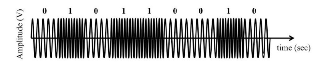
Frequency-shift keying (FSK) is a frequency modulation scheme in which digital information is transmitted through discrete frequency changes (shifts) of a carrier wave. The simplest form of FSK is binary FSK (BFSK), in which carrier wave is shifted to low or high frequency to transmit 0s or 1s.
Tags:
Source:
RF Theory
Amplitude Shift Keying (ASK)
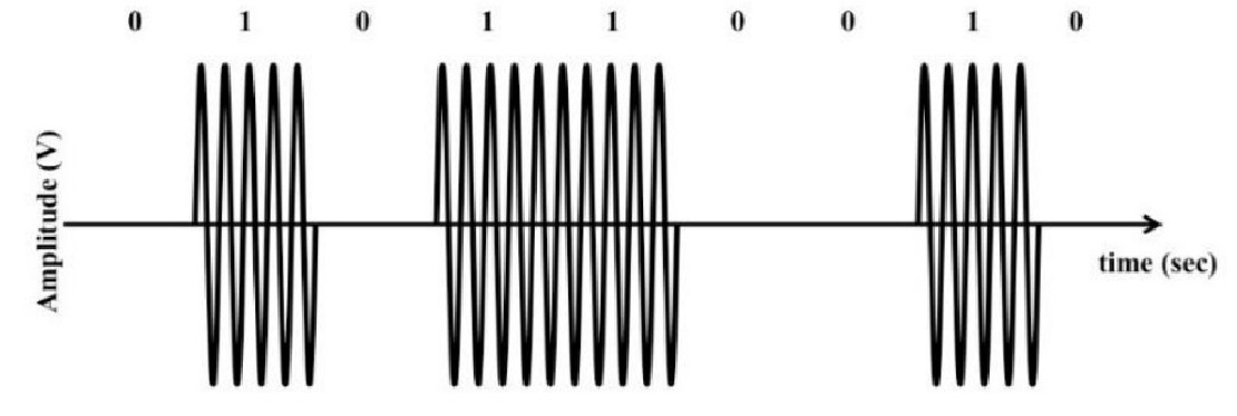
Amplitude shift keying is a form of amplitude modulation that represents digital data as shifts in the amplitude of the carrier wave. For example, a small amplitude represents 0, a large amplitude represents 1.
Tags:
Source:
RF Theory
On-Off Keying (OOK)
The simplest ASK modulation scheme is On-Off Keying (OOK), in which a carrier wave is transmitted for 1 and nothing is transmitted for 0.
Tags:
Source:
RF Theory
Binary Phase Shift Keying (BPSK)
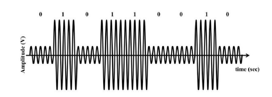
Binary phase shift keying (PBSK) is a phase modulation scheme where digital information (0s and 1s) is represented by shifting the carrier wave phase between two allowed values.
Tags:
Source:
RF Theory
Comparison of Digital Modulation Schemes
Tags:
Source:
RF Theory
M-ary Digital Modulation
M-ary digital modulation schemes are a set of modulation schemes that use more than one symbol (0 or 1 typical for binary modulation schemes). This means that for each symbol, more than one bit can be trasmitted at a time.
Tags:
Source:
RF Theory
Whitening Transformation of Data
A whitening transformation or sphering transformation is a linear transformation that transforms a vector of random variables with a known covariance matrix into a set of new variables whose covariance is the identity matrix, meaning that they are uncorrelated and each have variance 1. Data whitening is a process of reducing data to white noise vector.
Tags:
Source:
RF Theory
Frequency-Hopping Spread Spectrum (FHSS)
Frequency-hopping spread spectrum (FHSS) is a method of transmitting radio signals by rapidly changing the carrier frequency among many distinct frequencies occupying a large spectral band. The changes are controlled by a code known to both transmitter and receiver. FHSS is used to avoid interference, to prevent eavesdropping, and to enable code-division multiple access (CDMA) communications.
Tags:
Source:
RF Theory
ISM Band
The ISM radio bands are portions of the radio spectrum reserved internationally for industrial, scientific and medical (ISM) purposes other than telecommunications. Examples of applications for the use of radio frequency (RF) energy in these bands include radio-frequency process heating, microwave ovens, and medical diathermy machines. The powerful emissions of these devices can create electromagnetic interference and disrupt radio communication using the same frequency, so these devices are limited to certain bands of frequencies. In general, communications equipment operating in these bands must tolerate any interference generated by ISM applications, and users have no regulatory protection from ISM device operation.
Tags:
Source:
RF Theory
ZigBee
ZigBee is a wireless 2.4 GHz standard built on IEEE 802.15.4.
It’s a mesh network, so each node in the network mesh can act as a wireless data endpoint or a repeater.
ZigBee is An alliance and a standard of cost and energy efficient mesh networks.
The Zigbee protocol allows the transmission of data over long distances by passing information through a mesh network of intermediate nodes to reach distant ones. Messages “hop” through intermediary radio nodes on the way to their destination.
Tags:
Source:
RF Theory
ZigBee
The Zigbee mesh configures itself automatically (self-forming) and will reconfigure dynamically to repair itself if nodes are disabled or removed (self-healing). A ZigBee network allows over 65000 nodes in the network. End devices that can sleep to extend battery life can participate in the mesh, but not extend it. DigiMesh®, Digi’s proprietary mesh networking technology, supports applications that require the entire mesh network to sleep.
Tags:
Source:
RF Theory
XBee
XBee is Digi’s own ZigBee based protocol.
XBee modules are embedded solutions providing wireless end-point connectivity to devices. These modules use the IEEE 802.15.4 networking protocol for fast point-to-multipoint or peer-to-peer networking. They are designed for high-throughput applications requiring low latency and predictable communication timing.
Tags:
Source:
RF Theory
XBee Families
Series 1: The easiest to use. No configuration needed. Plug & Play. Incompatible with Series 2 or higher.
ZB: Configurable, can run in a transparent mode or using AT commands.
2B: Improved power usage of the ZB family.
900MHz: Sold in Digimesh or Point to Multipoint firmware configuration. Highly customizable. 156 kbps data rate.
XSC: Similar to 900MHz, but sacrifice data rate for range. Up to 15 miles range with high gain antenna. 10 kbps data rate.
Tags:
Source:
RF Theory
XBee Transparent Mode
When operating in transparent mode, an XBee module acts as a serial line replacement. All data received through the serial input is immediately transmitted over the air to the device identified by Destination Address in memory. When the XBee module receives wireless data, it is sent out through the serial interface exactly at it is received. In fact, communication in transparent mode yields the same result as if the two modules were connected by a wire, but wireless communication makes that physical wire unnecessary.
Transparent mode is also referred to as AT mode. This mode of communication is compatible with any device can communicate over a serial interface.
Tags:
Source:
RF Theory
XBee Command vs API Mode
When it AT mode, the module can be placed into either Command mode or API mode. In Command mode, the destination address is sent via UART as dedicated command. In API mode, the destination address is contained in the sent packets, which allows to dynamically configure the destination address without having to enter the Command mode. API mode is also useful for configuration of remote modules.
Tags:
Source:
RF Theory
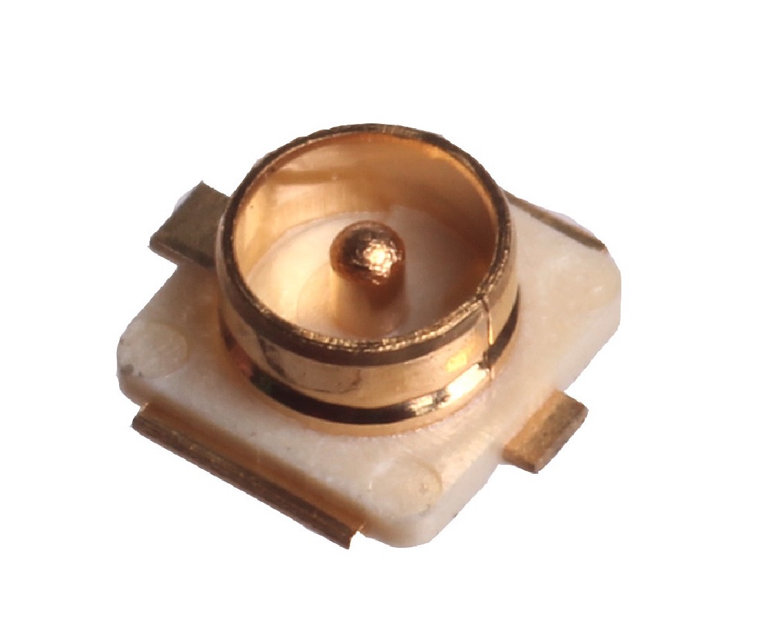
Hirose U.FL Connector
It is a miniature RF connector for high frequency signals up to 6 GHz. It is often used to connect WiFi antennas in embedded or limited space systems.
Tags:
Source:
RF Theory
Regular vs Pro XBee
There are a few difference between the regular XBees and the XBee Pros. The Pros are a bit longer, use more power and cost more money. The greater power means longer range (1 mile instead of 300ft). You can mix and match these on the same network.
Tags:
Source:
RF Theory
900 vs 2.4 XBee
Most of the Xbee modules operate at 2.4GHz, but there are a few that operate at 900MHz. Basically 900MHz can go a lot farther with a high gain antenna (up to 15miles for the Pro modules and a high gain antenna). Also the lower the frequency the greater penetration the signal has. 900MHz is also not allowed in many countries (although there are 868MHz versions available from Digi that are allowed in many other countries). You can NOT mix and match these on the same network.
Tags:
Source:
RF Theory
Bluetooth
Bluetooth is a personal area wireless networking protocol designed for communicating over short distances. It was originally created to replace the wiring needed to connect devices like computers and cell phones to their peripherals, such as headphones, keyboards and mice. It operates in the 2.4GHz frequency range, which is license-free globally.
Tags:
Source:
RF Theory
Bluetooth Classic
Bluetooth Classic is designed to steam high-throughput data at up to 2.1 Mbps over short distances where long battery life is not a major concern. It is an excellent solution for audio and video devices that require high-bandwidth and that can be recharged on a daily basis. Bluetooth uses a master/client architecture. One master may communicate with up to seven client devices in a small personal-area network.
Tags:
Source:
RF Theory
Bluetooth BLE
Bluetooth Low Energy supports low-bandwidth connections over short distances with excellent power management. It is used in situations where a personal-area network does not need to handle large data streams, and where batteries need to last months or even years. BLE is a point-to-point protocol. Therefore, radios cannot communicate beyond their individual range. This limits the physical size of networks to BLE’s typical 10-meter range.
Tags:
Source:
RF Theory
Bluetooth Mesh
It extends simple point-to-point BLE using additional routing and network formation standards to create mesh networks where nodes can act as relays to extend the network beyond the range of any one device. BT Mesh is broadly similar to Zigbee in overall function and architecture, but with several very important differences. A BT Mesh network can theoretically support over 32 thousand nodes.
Tags:
Source:
RF Theory
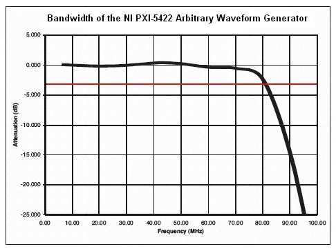
Bandwidth
The bandwidth of a signal generator is the frequency at which the output signal is attenuated 3 dB relative to the amplitude of a DC or low frequency signal. The picture below shows a function generator with bandwidth of 80 Mhz.
Tags:
Source:
RF Theory
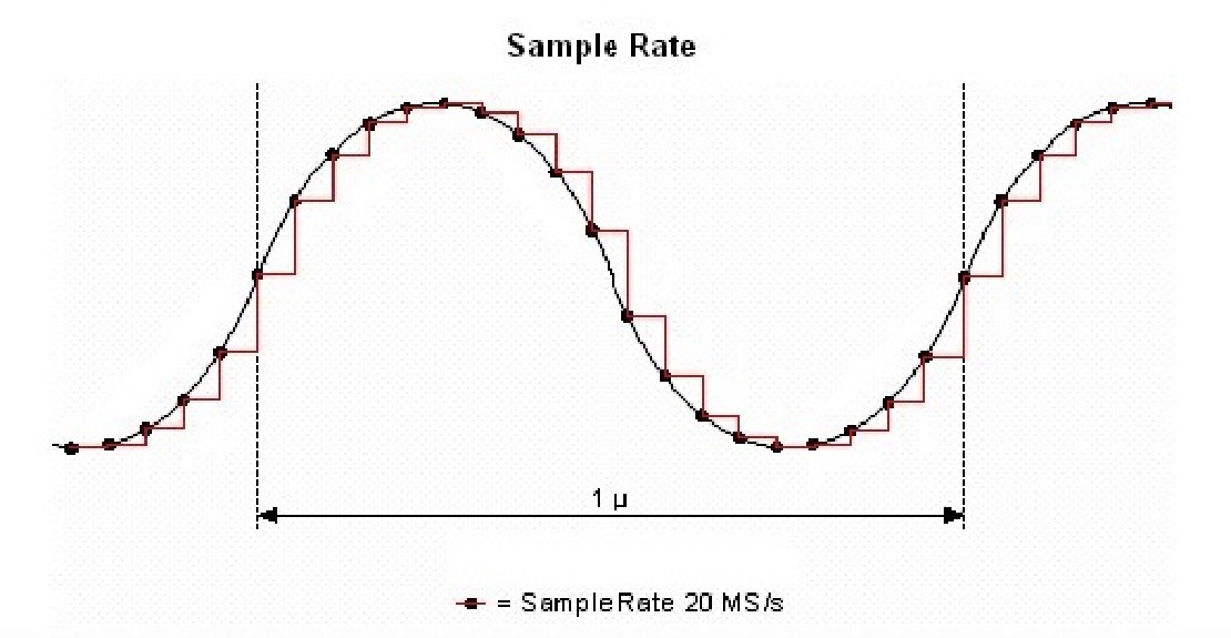
Sampling Rate
A digital waveform must be updated at least twice as fast as the highest frequency (Nyquist frequency) of the desired signal to be accurately generated. Ideally, though, a sample rate many times greater than the signal’s highest frequency produces accurate waveforms. A higher sample rate also captures more waveform details.
Tags:
Source:
RF Theory
True RMS
RMS measurements of sine waves in instruments use the peak voltage value to compute the DC equivalent value. The formula is Vrms = Vpeak * 0.707. These measurements are never perfect due to systemic noise. True RMS instruments take multiple measurements along the sine wave to reconstruct more accurate representation of the sine wave.
Tags:
Source:
RF Theory
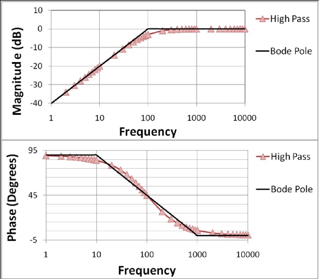
Bode Plot
In electrical engineering and control theory, a Bode plot /ˈboʊdi/ is a graph of the frequency response of a system. It is usually a combination of a Bode magnitude plot, expressing the magnitude (usually in decibels) of the frequency response, and a Bode phase plot, expressing the phase shift.
Tags:
Source:
RF Theory
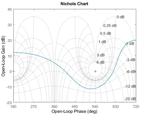
Nichols Plot
A Nichols chart displays the magnitude (in dB) plotted against the phase (in degrees) of the system response.
Tags:
Source:
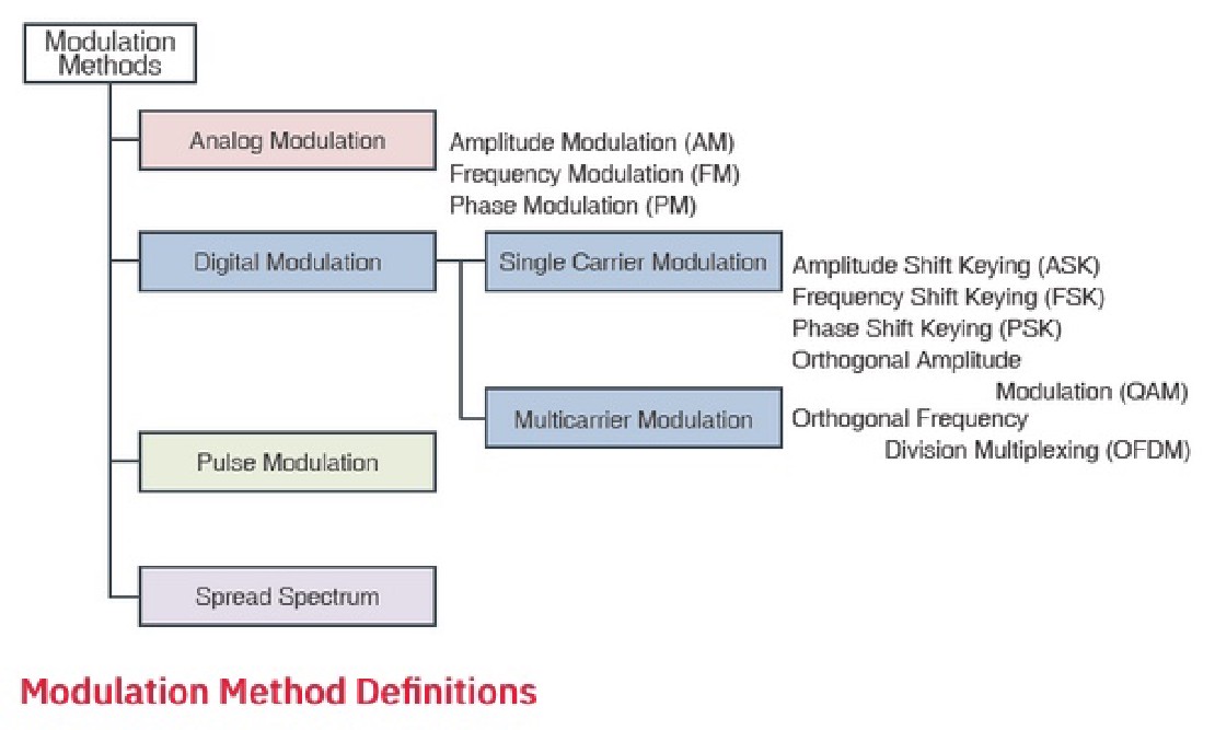
RF Theory
Modulation Techniques
Tags:
Source: